Several pieces of equipment common in chemical and power plants are there to separate liquid from vapor or vapor from liquid. This is an important process because the dispersed phase can have undesirable effects. The effluent from a fossil fuel burning power plant, for instance, may contain sulfuric acid droplets, or other undesirable materials. Steam which has a little moisture entrained in it can leave undesirable silica deposits on superheater tubes. Water carried over into a turbine from a boiler can erode the blades and cause them to fail. There are many occasions when removing liquid from a gas stream or gas from a liquid stream is required.
A variety of techniques exist for doing this. For the smallest drops (less than 10 microns) fiber mist eliminators are used. As the particles become larger, impingement devices like screens are adopted. As they get still larger, chevrons are used. Finally, for the larger drops, cyclones are adopted. They can operate for the entire range of liquid-to-gas-phase flow rates.
For a first pass at the selection of a suitable separator system, see Figure 1. Phase Separation Overview should also be consulted. The most important parameter is the drop or particle size with 10 microns (10 × 10−6 m) being the dividing line between the particles which can be separated by inertial means using cyclones or chevrons, and those which are so small that filters or other means based on diffusion must be used.
An example of a separator system which has been used for steam and water at. elevated pressure is shown in Figure 1, Young et al. (1980). A steam/water mixture enters the vertical pipe at the lower center of the figure. It passes through the swirler in the center which throws most of the liquid onto the walls of the central tube. Just after the swirler, the separated liquid is removed through holes in the walls of the central tube. The steam and remaining spray passes into a plenum which allows further liquid removal by gravity. The removed liquid drains onto the small tube which is at the right of the central tube. The remaining mist and vapor proceeds up into the dryer near the top of the vessel where an impingement separator removes most of the remaining liquid. The almost dry vapor then proceeds into the discharge shown at the top of the figure. The principles of gravity, swirl, and impingement separation are all illustrated in this installation.
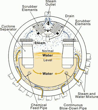
A system which has different geometric constraints is illustrated in Figure 2. Head room is limited in a steam drum so the liquid and vapor from many heated tubes enter at the bottom, pass up into the periphery into a double row of cyclone separators. Almost dry steam leaves out of the top of the cyclone while the separated liquid leaves the bottom. The almost-dry steam proceeds to the scrubber section (usually chevrons) and then out of the drum to the superheater.

Figure 2. Steam drum separator section typical of modern drum type natural circulation boilers. Avallone, et al. (1987).
The mass flow rate of drops less than 10 microns in diameter is quite small in typical steam generation installations so the mass fraction of liquid flowing out of the separator section for installation of this type is typically of the order of 0.1 percent.
For chemical plant installations in which the drops consist of fumes of toxic substances like sulfuric acid, better separation efficiencies are required. For this a fiber mist eliminator is desirable. This type of separator is the only one which will work on fume particles as small as 0.1 microns.
Separation can be a problem when some vapor is entrained with liquid, such as when a jet or stream of liquid enters a pool. This is called carryunder. To prevent carryunder from being a problem, the liquid flow rate down in the pool must be kept well below the bubble rise velocity; that is, the velocity down for the liquid should be less than 0.2 m/s.
In the remainder of this section, the types of separators will be described in greater detail, their limitations and characteristics mentioned, and guidelines for selection given.
The simplest separator is the gravity separator. The rule of thumb used to size a gravity separator is that the superficial velocity of vapor at the free surface should be less than 0.3 m/s. When the velocity is greater than this, the carryover increases rapidly. Kataoka, et al. (1981) describe the carryover process in some detail. Often these separators are constructed as large-diameter inclined pipes in which the two-phase mixture enters at the bottom of the high end, and separated liquid is removed from the bottom of the low end. Vapor is removed from the top of the high end. In excess of 99 percent of the entrained liquid can be removed in gravity separators though some small drops are carried over for all flow rates. These separators can be horizontal or vertical cylinders or spheres.
When a gravity separator is overloaded, the distinct interface between the liquid and vapor disappears, and a large amount of liquid is carried over. A distinct interface between the liquid-rich and vapor-rich regions always disappears by the time the superficial velocity of vapor is greater than 2 m/s.
Centrifugal separators have a higher characteristic throughout and have the unique characteristic in that they can be used to separate any proportions of liquid or vapor in the incoming stream (see also Centrifuges). The flow regime in the incoming stream doesn't matter. When they are used within their design envelope, they effectively separate 99 percent of the liquid. Drops that are less than 10 microns in diameter are not usually separated. The pressure drop in these separators tends to be larger than in other kind because the characteristic velocity is larger. The swirler shown in the center of Figure 1 is typical of centrifugal separators.
When a cyclone separator is overloaded, the pressure in the swirl chamber drops so much below that of the pool into which the separated liquid drains that the liquid rises up the down commer and floods the separator.
Chevrons and screens operate by intercepting drops which are unable to follow the vapor as it goes through a tortuous path through the device. These separators work on dispersed flows and are generally ineffective on drops less than 10 microns in diameter. Figure 3 shows how the chevrons are arranged. Vapor flow is in the horizontal plane while the separated liquid runs down due to gravity normal to the page.
When a chevron separator is overloaded, the liquid is re-entrained before it can drain away. Knitted wire mesh separators perform much the way chevron separators do except that they have lower characteristic velocities in them but can trap smaller drops. They fail when overloaded in the same way that chevron separators do, the separated liquid is re-entrained before the liquid can drain away.
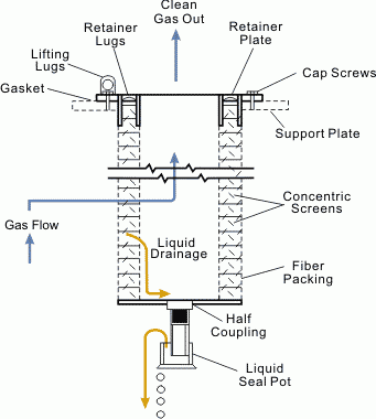
Mist eliminators are particularly well adapted to the elimination of drops smaller than 10 microns. They consist of a mat or bundle of fibers arranged so that the separated liquid can drain away easily, and the gas can continue on through the filter material (see Figure 4). As the velocity through these separators increases, they also fail in the same way as the wire mesh or chevron separators, the liquid is re-entrained before it has a chance to drain away.
Pressure drop in separators is the penalty we must pay to separate the two phases. It is important to be able to estimate the pressure drops through the separator and select a separator type which is suitable for the application in question. Table 1 summarizes the performance of these kinds of separators in terms of the dimensional quantity given below.

in which the characteristic velocity is the velocity into the separator.
In this equation
F is a dimensional constant in m/s(kg/m3)1/2
vg = Vapor-phase velocity in m/s
pg = Vapor density in kg/m3
Extensive information on pressure drops and separation efficiency for various kinds of separators is available in Idelchik (1986), Perry, et al. (1973), and Carson, et al. (1980).
REFERENCES
Avallone, E., Baumeister, M. F. (1987) Mark's Standard Handbook for Mechanical Engineers, 9th edn.
Carson, W. R., Williams, H. K. (1980) Method of Reducing Carryover and Reducing Pressure Drop Through Steam Separators, EPRfNP-1607 Publishing Corp.
Idelchik, I. E. (1986) Handbook of Hydraulic Resistance, Ch 12, Hemisphere.
Katooha, R., Ishu, M. (1983). Mechanistic Modeling and Correlations for Pool Entrainment Phenomenon, NUREC/CR-3304
Moore, M. J., Sieverding, C. H. (1976) Two-Phase Steam Flow in Turbines and Separators, 340 Hemisphere.
Perry, R. H., Chilton, C. H. (1973) Chemical Engineers' Handbook, 5th edn., 18-88 McGraw-Hill.
Young, M. Y., Takeuchi, Mendler, D. J., Hopkins, C. W. (1984) Prototypical Steam Generator Transient Test Program: Test Plan/Scaling Analysis, EPRINP-3994, NUREG/CR 3661, WCAP-10475, (1973).
References
- Avallone, E., Baumeister, M. F. (1987) Mark's Standard Handbook for Mechanical Engineers, 9th edn.
- Carson, W. R., Williams, H. K. (1980) Method of Reducing Carryover and Reducing Pressure Drop Through Steam Separators, EPRfNP-1607 Publishing Corp.
- Idelchik, I. E. (1986) Handbook of Hydraulic Resistance, Ch 12, Hemisphere.
- Katooha, R., Ishu, M. (1983). Mechanistic Modeling and Correlations for Pool Entrainment Phenomenon, NUREC/CR-3304
- Moore, M. J., Sieverding, C. H. (1976) Two-Phase Steam Flow in Turbines and Separators, 340 Hemisphere.
- Perry, R. H., Chilton, C. H. (1973) Chemical Engineers' Handbook, 5th edn., 18-88 McGraw-Hill.
- Young, M. Y., Takeuchi, Mendler, D. J., Hopkins, C. W. (1984) Prototypical Steam Generator Transient Test Program: Test Plan/Scaling Analysis, EPRINP-3994, NUREG/CR 3661, WCAP-10475, (1973).


