Fluidics represents a family of process equipment which may be used to intensify a range of heat and mass transfer processes. The common theme connecting all fluidic items is the absence of packings and of moving parts within the equipment. The technology was developed initially to meet the needs of the UK nuclear industry to pump radioactive liquors using equipment of assured reliability. These applications are described by Etherington (1984).
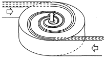
The vortex represents the basis of all Fluidic heat and mass transfer equipment. The vortex chamber (Figure 1) is used as an intense short residence time mixer. Flows are introduced to the chamber tangentially at the periphery. Under conservation of angular momentum, the fluid accelerates towards the outlet port on the center-line [see Stairmand (1990)]. This arrangement offers homogenization of the fluids within a residence time of several milliseconds. The vortex mixer has been used for precipitation, liquor blending and in-line gas-liquid mixing.
The draft tube mixer (Figure 2) is frequently used downstream of the vortex mixer to provide an extended residence time. A jet flow enters a central tube and also entrains liquor from the outside of the tube. Thus, a torroidal vortex is set up with a flow greatly larger than the feed jet. This creates a uniform mixing over residence times of order 10's of minutes. The duties to which the draft tube mixer has been applied are precipitate ripening, gas disolution and solvent extraction. Heat transfer may be effected by the use of an internal coil outside the draft tube, or by a jacket.
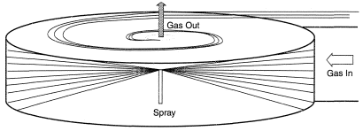
The vortex chamber is also used for gas-liquid contacting duties such as scrubbers, strippers and distillers. A radial spray head on the center-line of the chamber (Figure 3), creates a stream of droplets which hit the walls, ceiling and floor of the chamber. The droplet diameter is typically 0.3 mm and the velocity 15 m/s. Gas is introduced tangentially at the chamber periphery, establishes a vortex flow pattern, and exits on the center-line. This creates a countercurrent contact between the liquor and gas at droplet Reynolds numbers of order 103. Gas mass transfer rates are therefore high and the equipment is typically a factor of 5 smaller than conventional gas-liquid contactors for gas-side limited systems. In the case of some liquid-side limited systems, the performance of the fluidic gas-liquid contactor can be maintained by recycling the liquor. In addition to its application as a scrubber, the unit has been used for stripping organics from process liquors and, in a staged form, for carrying out distillation duties.
REFERENCES
Etherington C. (1984) Power fluidics technology and its application in the nuclear industry, Nucl. Energy, 23(4), 227-235.
Stairmand J. W. (1990) Plow patterns in vortex chambers for nuclear duties, Nucl. Energy, 29(6), 413-418.
Использованная литература
- Etherington C. (1984) Power fluidics technology and its application in the nuclear industry, Nucl. Energy, 23(4), 227-235.
- Stairmand J. W. (1990) Plow patterns in vortex chambers for nuclear duties, Nucl. Energy, 29(6), 413-418.


