The technology of fibre optics refers to the transmission of information, encoded within a light signal, along a suitable waveguide. The transmission medium is normally an optical fibre fabricated from silica. Transmission along a fibre relies upon a difference in Refractive Index between the core and cladding. Provided the refractive index of the core is higher than the that of the cladding total internal reflection can occur. (See also Reflectivity.)
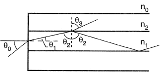
When the incidence angle (θ0) of the incoming light is below a limiting value known as the maximum acceptance angle, light follows the path shown by θ1, θ2 in Figure 1. The refractive indices of the fibre core, cladding and surrounding air are n1, n2, and n0, respectively. At larger incident angles some light escapes (θ3). A more detailed description of this topic is given by Dunlop and Smith (1989). For singlemode fibre the core diameter is much smaller than the cladding diameter (9μm cp 125 μm). This allows only the fundamental (LP01) mode to propagate at normal operating wavelengths. Multimode fibre contains a larger core diameter (for example, 50 μm) and allows higher order modes (LP11...) to propagate.
The transmission capacity of a an optical fibre is bounded by modal bandwidth, chromatic dispersion and attenuation. In a multimode fibre, the time taken for the fundamental and higher order modes to travel along the fibre differs as the path lengths vary. This gives rise to modal dispersion and so limits bandwith to the order of 1000 MHz.km. This phenomenon is absent in single mode fibres which are partially limited by chromatic dispersion. Chromatic dispersion is wavelength dependent and is given by the sum of the waveguide and material dispersions for the fibre. Because these vary with wavelength in an opposite sense a zero dispersion point occurs close to 1300 nm for conventional step index fibre.
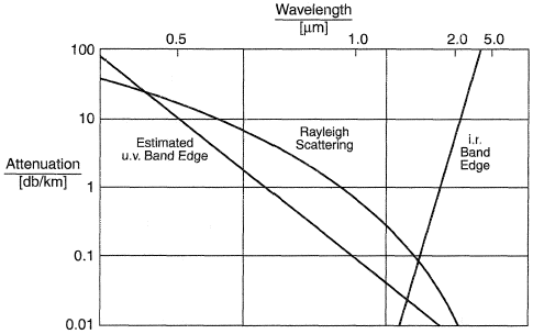
Fibre attenuation has fallen from 20 dB/km (1970) to 0.2 dB/ km (1985). The loss mechanisms arise from three absorption characteristics. Firstly, ultraviolet resonances increase significantly below 1000 nm. This is associated with electronic structure of the silica lattice atoms. Secondly, an infrared absorption increases beyond 1500 nm, caused by oxide bond vibration. This leaves the basic loss mechanism known as Rayleigh scattering. For high silica based fibres, this is the dominant loss mechanism in the 1300 to 1600 nm region. The Rayleigh scattering loss, LR (dB/km) is expressed as:

where A is the scattering coefficient with values in the range 1–1.6 dB/km-μm−4, λ is wavelength.
The most significant extrinsic loss is that due to OH. The overtone absorption bands occurring due to water in silica have combination bands at 1.24 μm. When this consideration is combined with the intrinsic loss behavior the favored transmission windows become 1260-1360 nm and 1480-1580 nm.
Bulk silica has a tensile strength of approximately 14 GPa. However, the strength of silica based fibres is dominated by extrinsic flaws in the fibre surface. The distribution of flaws on the surface may be quantified and so the probability F of a fibre failing at or below a stress, Si is given by the Weibull equation:

where L0 is a standard length, S0 and m are the Weibull shape and scale constants, respectively. The depth of the flaws grows under applied strain and in the presence of agents which increase the stress corrosion susceptibility constant (n) of the fibre. Note that as the dimensionless unit n decreases, the rate of flaw growth increases. For a fibre with original inert strength Si experiencing a constant stress S the time to failure, tf, is given by:

B is a material constant derived during inert strength measurements.

Figure 2. Extrinsic loss behavior from Gowar, J. (1983), Optical Communication Systems, Prentice Hall, Kernel Hampstead, UK, with permission from the publisher.
Typically Si, under inert conditions, is 14 GPa, B is 1010 Pa2s and n is 20.
The installation of fibre into communications networks requires fibre to be coated with buffering materials to allow cabling into robust structures which can be pulled into underground ducts or directly buried. Bark and Lawrence (1987) discuss generic cable designs. Alternatively, groups of fibres can be blown into preinstalled tubing [see Cassidy and Hornung ( 1984)].
REFERENCES
Dunlop, J. and Smith D. G. (1989) Optical Fibre Communications, Chapter 12, Telecommunications Engineering, Van Nostrand Reinhold International.
Gowar, J. (1983) Optical Communication Systems, Chapter 3, Prentice-Hall International.
Bark, P. R. and Lawrence, D. O. (1987) Fibre Optic Cables: Design, Performance Characteristics, and Field Experience, Chapter 5, Optical Fibre Transmission, E. E. Basch, Ed. Howard W Sams & Co.
Cassidy S. A. and Hornung S. (1984) A Fibre Unit for Blown Fibre Cable IEE Colloquium on Implementation and Reliability of Optical Fibre Cable Link, London.
Использованная литература
- Dunlop, J. and Smith D. G. (1989) Optical Fibre Communications, Chapter 12, Telecommunications Engineering, Van Nostrand Reinhold International.
- Gowar, J. (1983) Optical Communication Systems, Chapter 3, Prentice-Hall International.
- Bark, P. R. and Lawrence, D. O. (1987) Fibre Optic Cables: Design, Performance Characteristics, and Field Experience, Chapter 5, Optical Fibre Transmission, E. E. Basch, Ed. Howard W Sams & Co.
- Cassidy S. A. and Hornung S. (1984) A Fibre Unit for Blown Fibre Cable IEE Colloquium on Implementation and Reliability of Optical Fibre Cable Link, London.
